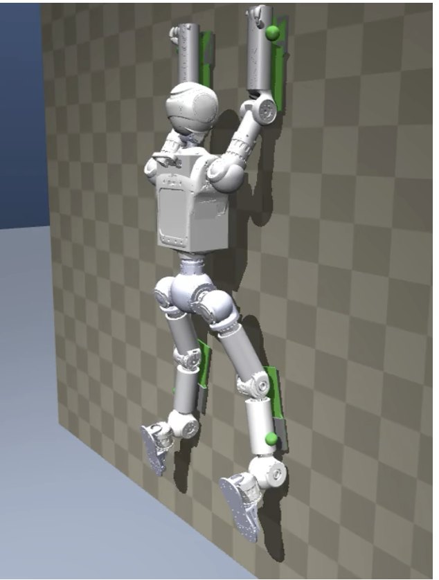
A generated reference up an exterior corner.
Every latch and release decided by the spine model.
Simulation · generated referenceReference only; see the status key
Humanoid Wall Climbing
A probabilistic model of micro-spine contact, spine palms designed with it, and whole-body references generated and certified under it, so a humanoid can learn to climb vertical walls.
Overview
Damaged structures, bridges and utility poles need inspection and maintenance on rough surfaces nobody prepared for a robot. A humanoid already walks and works with its hands on the ground; we want the same body on the wall. Micro-spines grip such surfaces, but they hold only when loaded the right way, and they let go at random. We model that randomness, design the palm with the model, and generate every motion the robot learns under it.
How the parts fit
One model throughout. The same spine model chooses the hinge, decides latches and releases inside the generator, scores each reference's reliability in its certificate, and runs in the training simulator.
Contact model
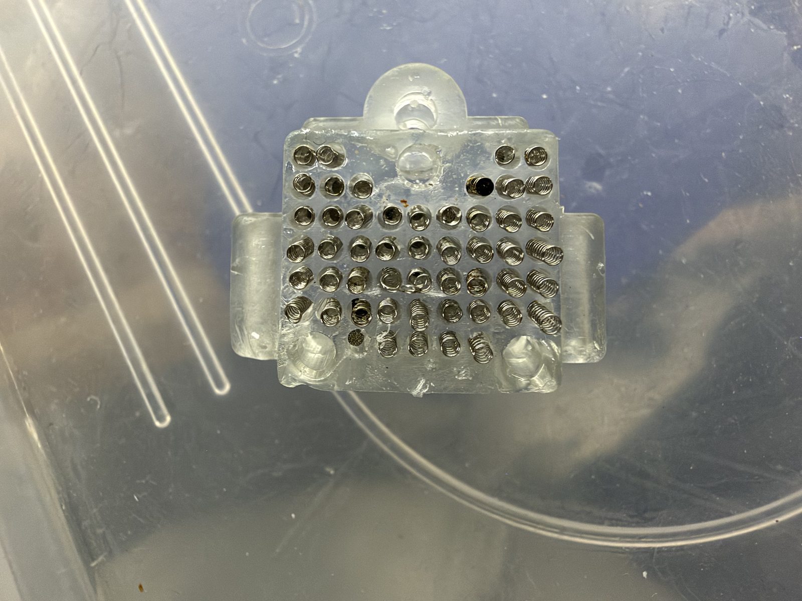
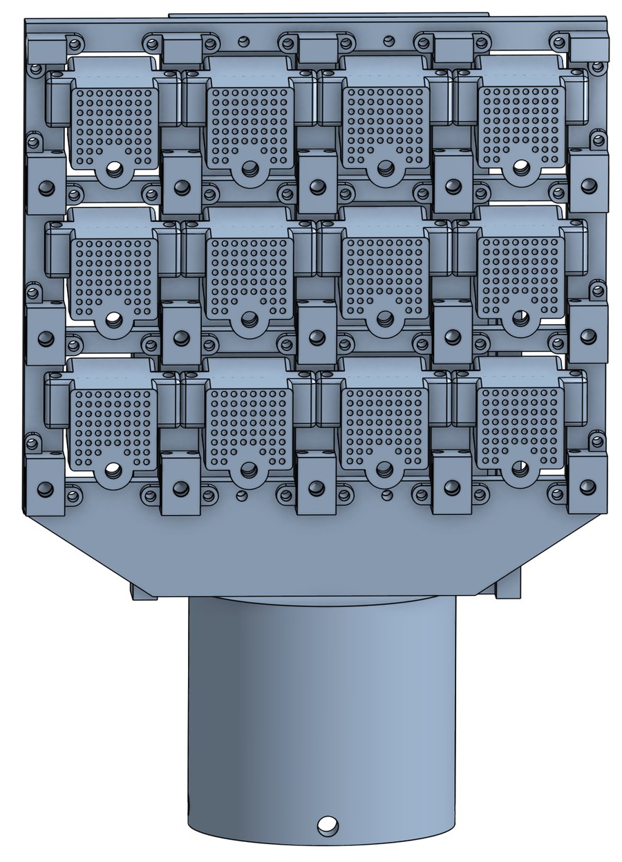
A spine palm is twelve spine units. We measured how a single unit lets go, then modeled how a palm fails as load shifts between its units. The same model runs in the palm design, the reference generator, its certificate and the training simulator.
The palm holds as long as enough units do. The model tracks which units still hold, how the load is shared among them, and every round in which they can let go.
A palm has \(N=12\) units. Their strengths are independent draws from one measured distribution, but their failure probabilities differ, because each unit carries its own load. A failed unit stays out until the palm latches again.
The palm's wrench about the array centre: \(x\) along the rake, \(y\) lateral, \(z\) out of the wall, so \(F_z>0\) pulls. \(A_i\) is rigid-palm, equal-stiffness bolt-group statics over the units still holding, so it changes whenever one fails; failed units carry nothing.
On a rough surface some units never catch: on the bench they let go while the shear and lateral load were still being applied, and \(p_{\mathrm{early}}\) is that share at each tested load. Each unit faces this Bernoulli trial once per latch, at its first load with every unit in place.
\(Q\) is the measured inverse CDF of a unit's pull-off force at that shear and lateral load. A unit keeps its rank \(U_i\) through every load of a latch. It fails when its pull exceeds \(C_i\), or when its shear and lateral load leave the tested range.
From a branch with mass \(m\) and survivors \(S\), exactly the subset \(B\) fails in the next round. Strengths persist, so \(q_i\) is conditional: \(a_i\) is the largest \(\alpha_i\) the unit has already held, and a load it has held before adds no hazard. All of \(B\) leaves before the load is shared again.
A branch ends when a round removes no unit, or at the first release state. \(\mathcal D\) holds those states: fewer than three units, or units all on one line, which cannot carry a moment in every direction.
\(T\) runs the cascade on fixed ranks from the screened state \(\mathbf e_0\). The simulator never evaluates \(\pi\): each latch draws its ranks and early-failure variates once, and one GPU thread runs \(T\) in every 10 ms hold window, so the rollouts themselves sample \(\pi\). Only the load-independent geometry of all \(2^{12}=4096\) survivor sets is precomputed.
A spine catches on a tiny bump when it is dragged the right way. Real walls are irregular, so not every spine finds one at once. Each spine rides on its own spring and moves on its own, so more of them end up in contact.1
 One spine unit
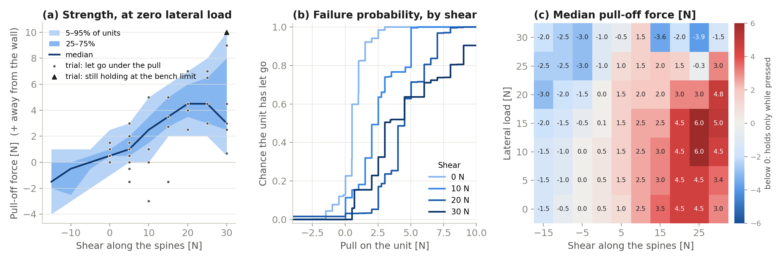
A Rizon arm presses one unit onto a cinder block under force control. After a 10 N preload, the shear and lateral loads ramp to a test point; the normal force then steps down through zero and into tension, 0.5 N every 3 s, until the unit lets go.
With enough shear along the spines, a unit keeps holding while it is pulled away from the wall. Against the rake it holds only while pressed.
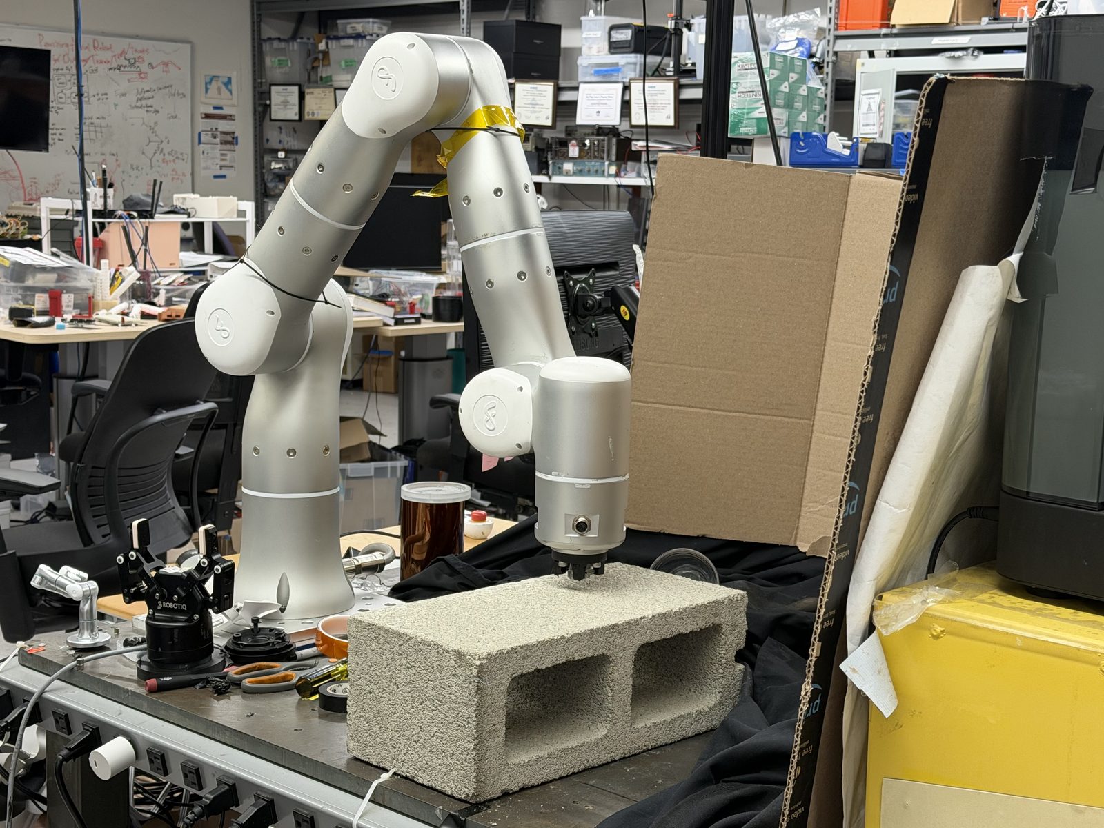
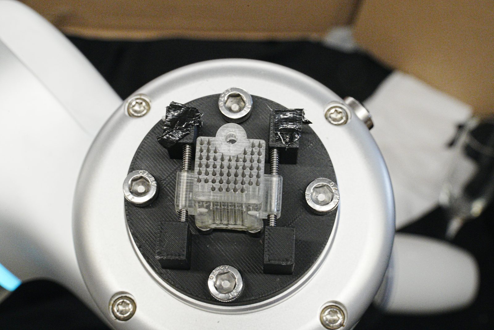
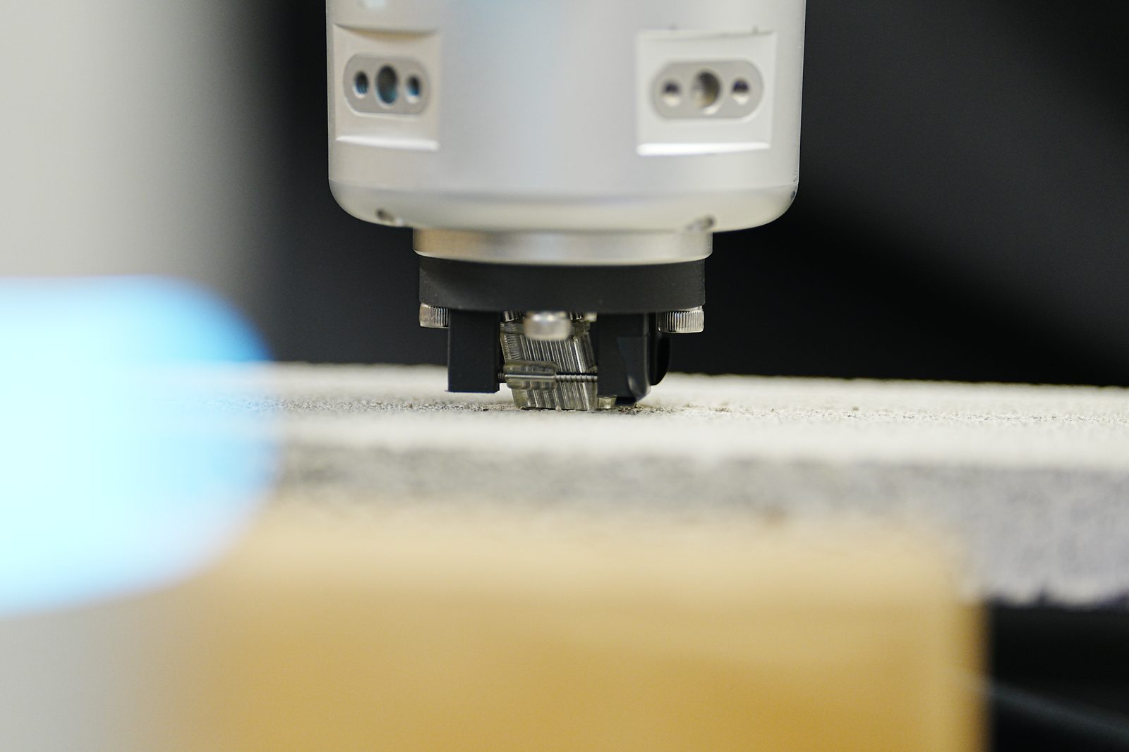
A cinder block flipped with a spine palm. In simulation the palm touches down, latches, lifts the block and releases it, the same sequence as on the bench.
One load case, round by round.
Swipe the animation sideways to read it.
The 3 × 4 palm seen from outside the wall, under an 8 N pull and 90 N of shear. Each round, overloaded units fail together and the load is shared again. Followed exactly, the tree gives a 58.4% chance that the palm holds; 600 draws, run the way the simulator runs them, give 56.3%.
Palm design
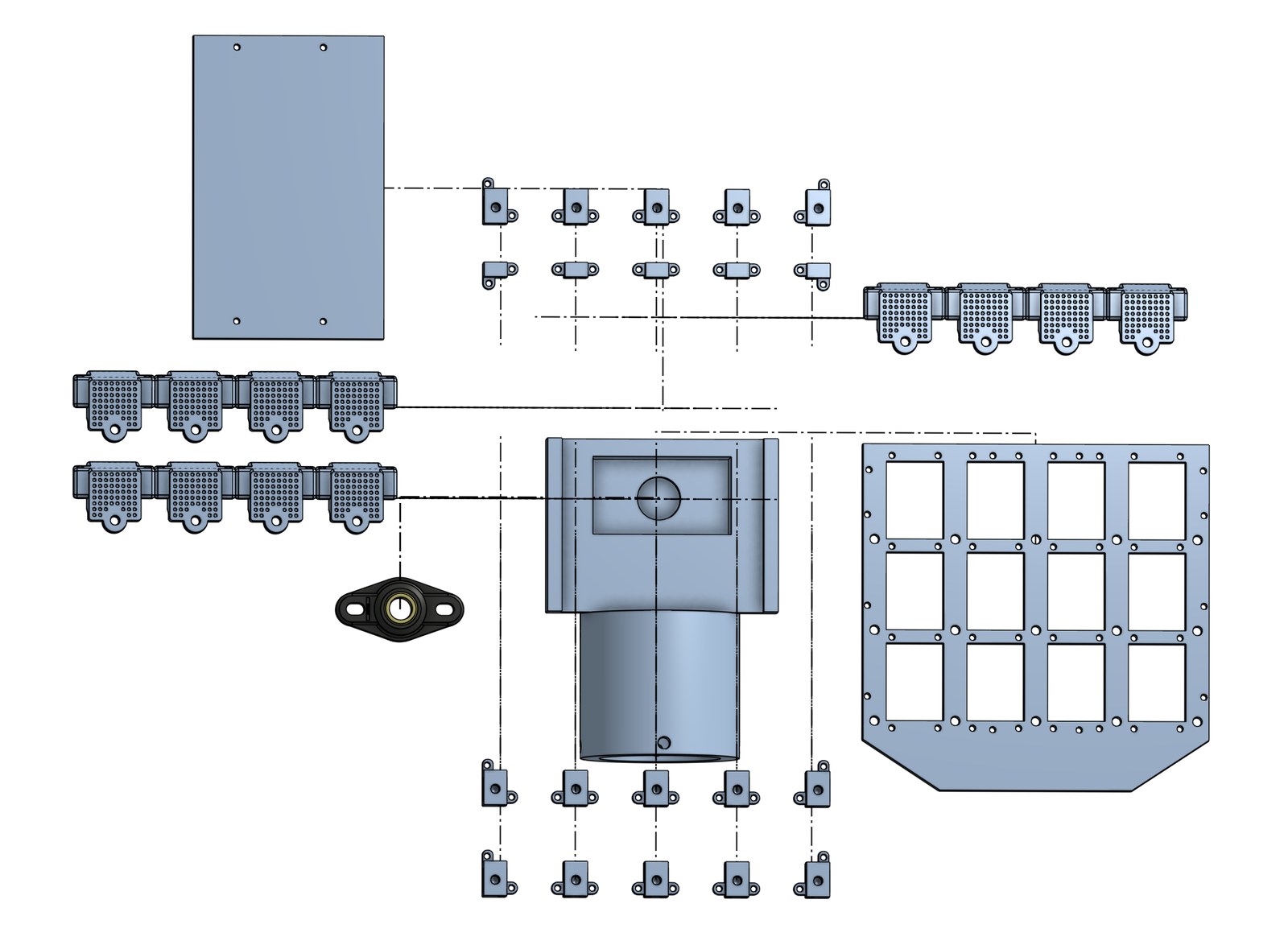
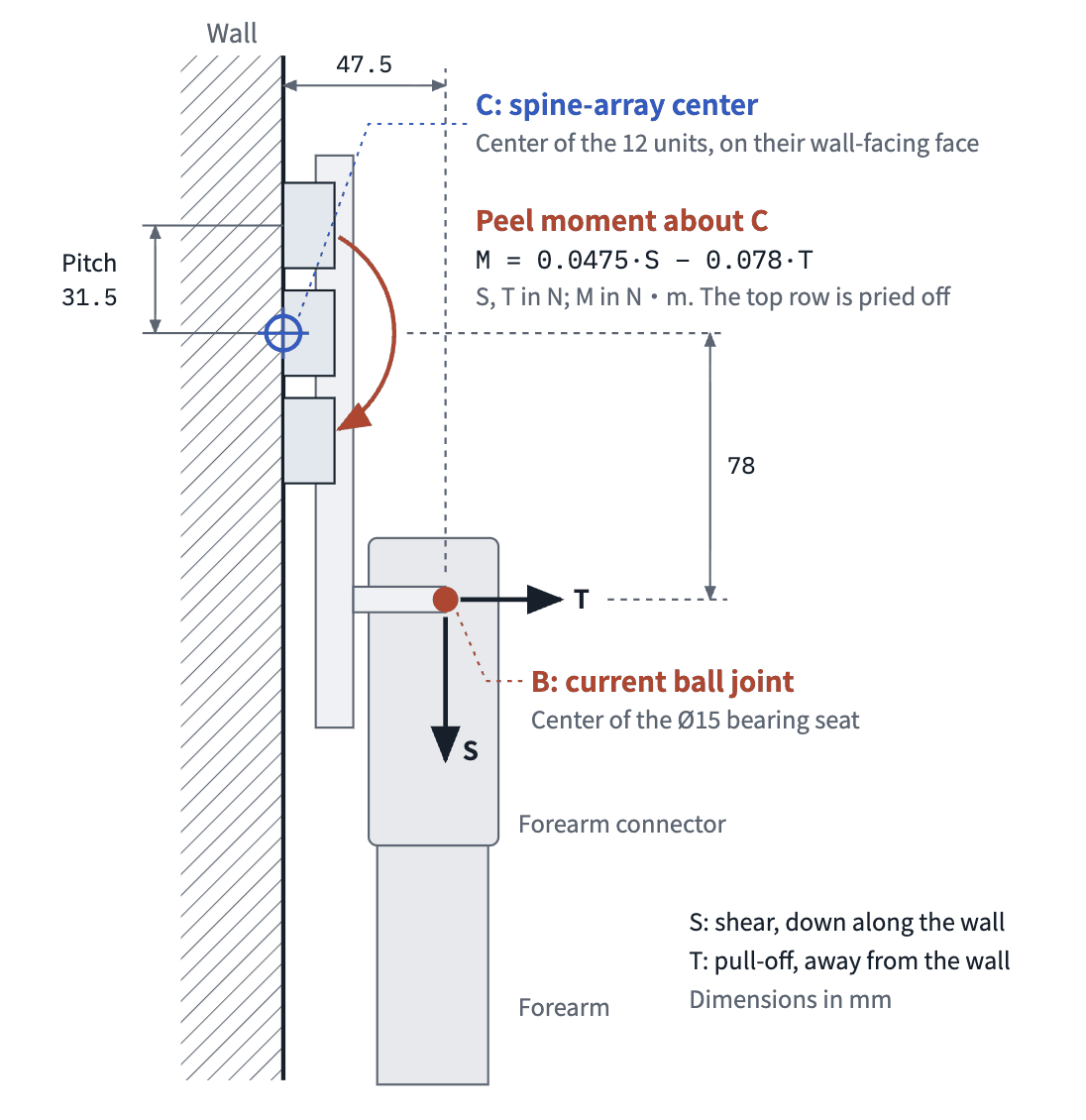
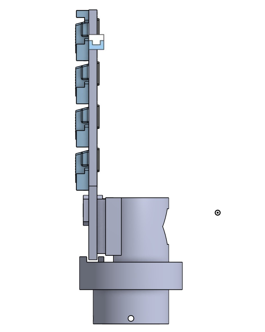
Twelve units share one plate that turns freely on the limb, so the limb passes only a force through the hinge. Where that hinge sits decides how the force reaches the units: above the spine face, shear becomes a peeling moment that lifts the top row; off centre along the face, the normal force does the same.
Each version moves the hinge toward the spine face. The second sits much closer than the first, but its force line still misses the array centre.
| S ↓ T → | −20press | 0 | 10 | 20 | 30 | 45 |
|---|---|---|---|---|---|---|
| 50 | 1.00 | 1.00 | 0.52 | 0.01 | 0 | 0 |
| 100 | 1.00 | 1.00 | 0.97 | 0.34 | 0.01 | 0 |
| 150 | 0.99 | 0.99 | 0.98 | 0.81 | 0.18 | 0 |
| 200 | 0.93 | 0.90 | 0.88 | 0.74 | 0.36 | 0.01 |
| 250 | 0.92 | 0.91 | 0.83 | 0.60 | 0.20 | 0.02 |
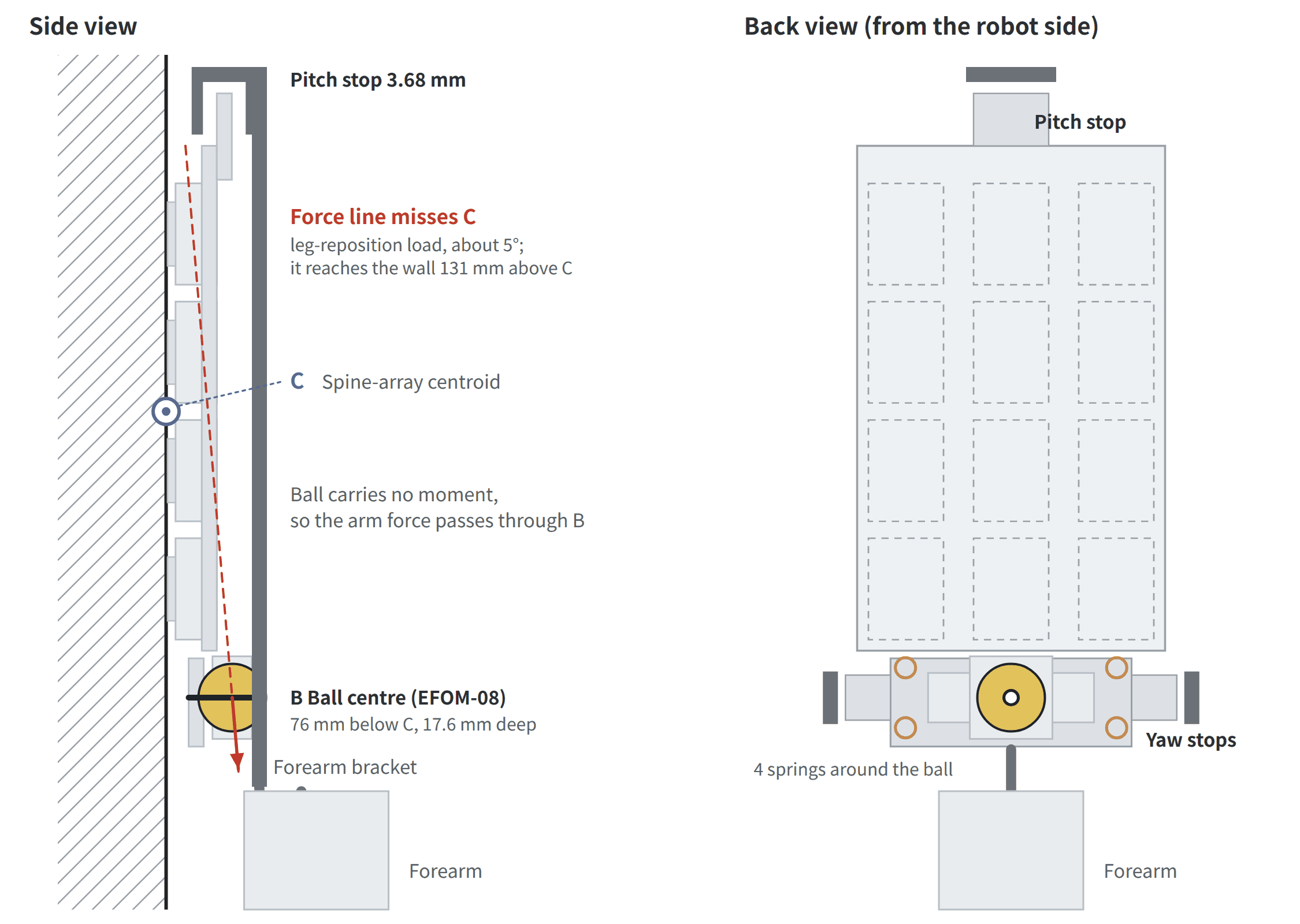
Every design variable stays inside what can be built: hinge geometry, stop angles and spring rates come from real parts.
One palm under 150 N of shear and no pull, 20,000 draws of unit strength. Height \(h\) is measured from the spine face.
Each millimetre of height adds about 0.6 N of pull on every top-row unit at this shear.
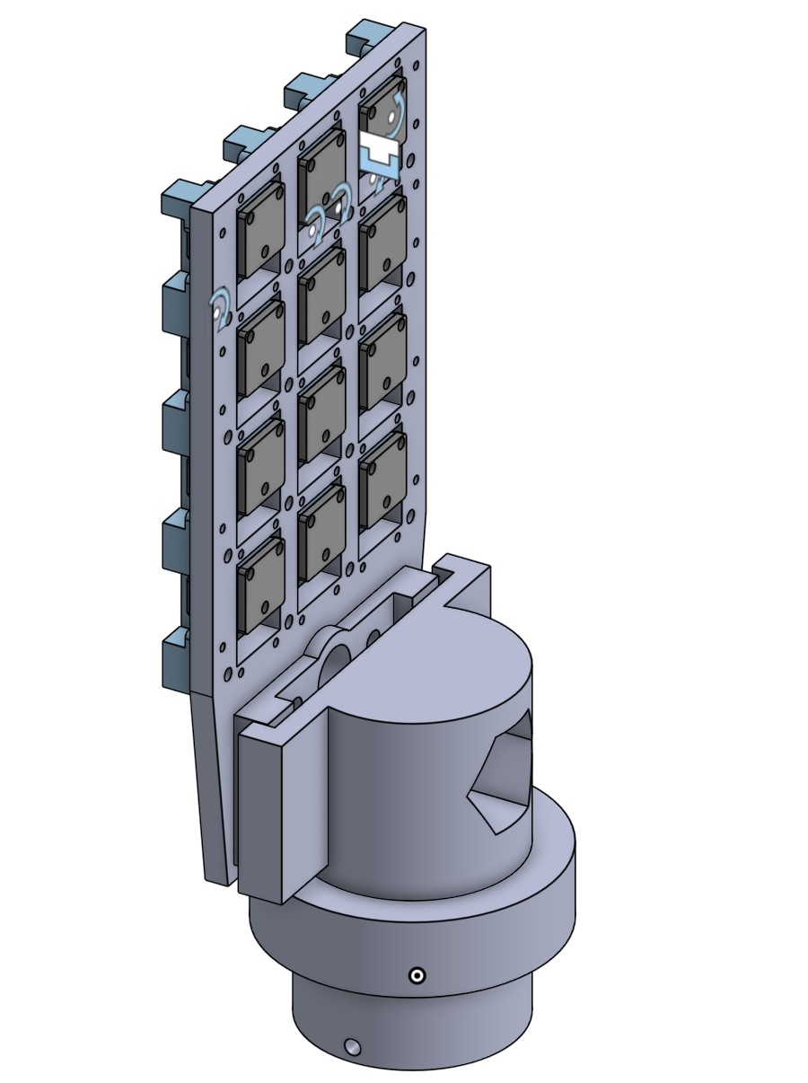
Two columns of six units clamp the wrist roll axis, with the palm centre level with it. A pin hangs the palm in a U-fork: it tilts ±6° on its stops and slides 2 mm along the normal on preloaded springs.
In fourteen corner load cases the forearm's three 9 N·m motors stay within their limits; a rigid flange mount exceeds them. Designed and checked in simulation.
Reference generation
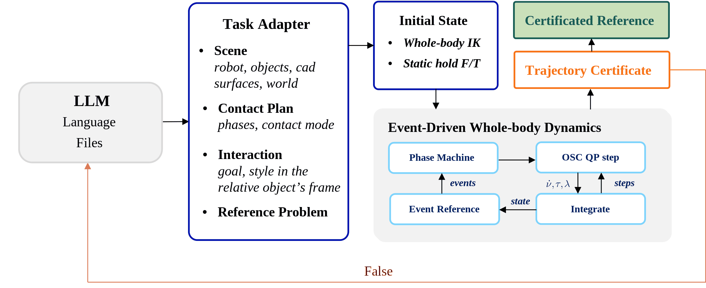
A spine palm latches only after enough preload, holds only while each unit stays inside its measured limits, and lets go when the load says so. A kinematic reference cannot know when any of that happens. We generate each reference as a whole-body dynamic trajectory under the training simulator's own contact rules, then certify it from the stored trajectory alone.
A task contributes only an adapter. Generation, the event rules and the certificate are the same code for every task. Select a block to see how it works.
Swipe the figure sideways, or pick a block below.
A task starts as a description and its files: the robot, the objects, the CAD of the surfaces to climb or grip. An LLM agent, or a person, writes the task adapter from them.
Upstream and optional, a GPU statics search chooses the pad design and a chain of whole-body static keyframes for the plan.
When a step is infeasible or a check fails, the generator reports the time, the phase, the conflicting constraints and the shortfall.
That report goes back to the task input. The design variables or the plan are revised, and generation resumes from the last phase checkpoint instead of from the start.
The same problem always gives the same bytes, so a reference is reproducible from its adapter alone.
Each integration step solves one QP; every 20 ms the plant decides what changed.
Each phase of the contact plan says which contacts are held and what the task asks for. It ends when its exit event fires, a latch, a release or a touchdown, never at a scheduled time.
The unknowns are the joint torques \(\tau\), the contact forces \(\lambda\) and the reactions \(r\) of passive joints held on their stops. The accelerations \(\dot v\) are eliminated through this equation, so it holds at every step.
\(\mathcal K\) is the friction cones and, for a latched spine palm, every unit's load inside its measured domain and a trust box around the current load.
\(J\) is the probability that every latched palm keeps holding. Each solve is checked against its KKT conditions, or the step fails.
The plant's failure cascade is run on 512 fixed draws of unit strength, with each of its rules softened so the result is smooth in the load. Near the current load it enters the QP as a quadratic model.
Contact drift is removed by a mass-weighted projection, and a passive joint that reaches its stop takes an inelastic impact. Every step stores \(q, v, \dot v, \tau, \lambda\), contact points, modes and events.
4,096 persistent realizations of a latched palm's units follow it through holding windows, early failures and cascades. Rigid parts touch down and lift off. Events end phases, so the plan never schedules a contact change that only the plant may decide.
Trust the trajectory, not the generator. The certificate reads only the stored trajectory and recomputes every claim with its own code.
A reference passes when all ten checks pass.
A legal release unhooks. The palm is pulled off along the normal during its unloading phase, while every unit still holding carries at most 0.2 N of shear along the spines. Pulling off under shear is a failure, not a release.
R1, per latch. Each of 65,536 realizations draws its unit strengths once and follows the stored loads through the plant's holding windows, failures and load sharing. It reports the share that hold through the phase, and the share that release legally.
R2, the whole task. Realizations that release legally are grouped by release step; each group resumes the generator from the unloading checkpoint and is certified again. Intervals are Clopper–Pearson.
A block flip with one hand, and a climbing cycle up an exterior corner, both on the 27-DoF robot with fork palms. Only the adapters differ.
Block flip completes (R2): the palm holds, releases legally and the block ends upright.
Corner cycle, all eight latches hold (product of R1 over the cycle). The weakest single latch, a foot, holds at 0.94.
Certificate checks pass on both. Half-step convergence (T8) is still open.3
Policy learning
Each skill is first learned by its own teacher, which tracks a certified reference and sees what only the simulator knows. All teachers are then distilled into one student that acts from proprioception and an operator's skill command.2
Stage I
Climbing down is generated, not replayed. A reversed climb would pull the spines against their rake, so every skill gets its own reference and certificate.
Stage II
Results
In the order a mission needs them: get from the ground onto the wall, then climb it. Both run in simulation with the spine model's random latches and failures.
Task 1
Standing on the floor, the policy places its hands and feet on an inclined wall, latching each palm on the way: the move every mission makes between ground and wall.
Task 2
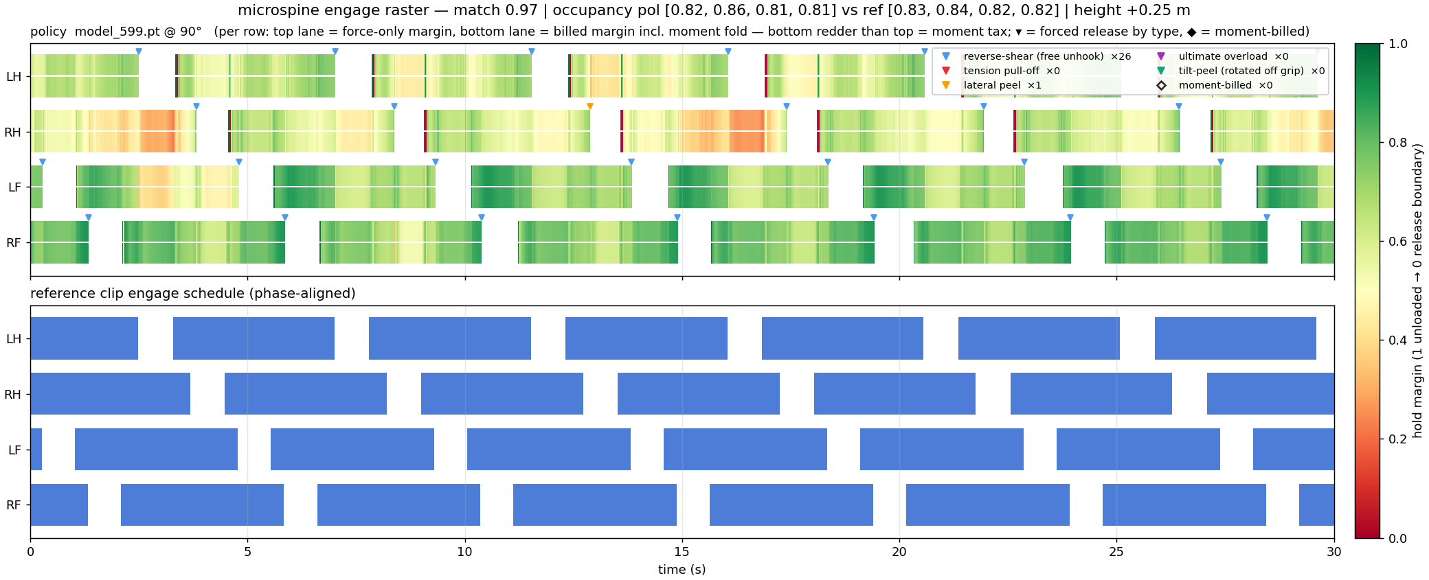
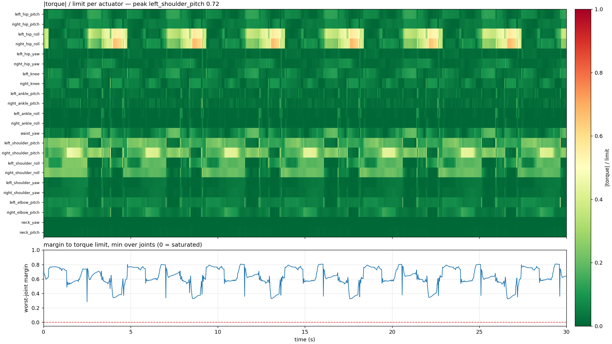
A teacher tracks a kinematic climbing cycle on a 90° wall. In a 30-second rollout its spine engagement follows the reference schedule closely, and no actuator goes above 72% of its torque limit.4
Engage-schedule match between the policy and the reference over the 30-second rollout.
Fraction of time each limb is engaged. The reference asks for 0.82–0.84.
Peak torque-to-limit ratio, at the left shoulder pitch. The most-loaded joint keeps a margin throughout.
Spines hold only when they engage on time and with enough preload. Two terms shape that.
When a limb's engagement disagrees with its engage gate for longer than a grace period, every tracking reward is discounted, down to a quarter.
\[\begin{gathered}m_h=\mathbf 1[\hat e_h\ne e_h]\cdot\min\!\Big(\frac{d_h\,T_{\mathrm{cyc}}}{\tau_g},\,1\Big)\\ G=f+(1-f)\Big(1-\frac1H\sum_h m_h\Big)\in[0.25,\,1]\end{gathered}\]with \(\tau_g=0.25\) s and \(f=0.25\). Joint-position, end-effector and root-orientation tracking are multiplied by \(G\):
\[\begin{aligned} r_{\mathrm{jpos}}&=\exp\!\big(-\tfrac{1}{\sigma^2}\,\mathrm{mean}_j(\hat q_j-q_j)^2\big)\cdot G\\ r_{\mathrm{jvel}}&=\exp\!\big(-\tfrac{1}{\sigma^2}\,\mathrm{mean}_j(\hat{\dot q}_j-\dot q_j)^2\big)\\ r_{\mathrm{ee}}&=\exp\!\big(-\tfrac{1}{\sigma^2}\,\mathrm{mean}_h\lVert\hat{\mathbf p}^r_h-\mathbf p^r_h\rVert^2\big)\cdot G\\ r_{\mathrm{ori}}&=\exp\!\big(-\tfrac{1}{\sigma^2}\,\theta_{\mathrm{geo}}(\hat q^{\mathrm{root}},q^{\mathrm{root}})^2\big)\cdot G \end{aligned}\]with \(\sigma\) = 0.2 rad, 1.5 rad/s, 0.1 m and 0.3 rad, in order.
Rewards pressing the palm into the wall, up to 12 N, while a limb is in its engage phase, or within 0.3 s of it, but not yet engaged. It shapes the preload that lets spines catch.
\[\begin{aligned}r_{\mathrm{press}}=\sum_h\ &\underbrace{\min\!\Big(\frac{F_h^{\mathrm{pad}}}{12\ \mathrm N},\,1\Big)}_{\text{press ratio}}\\ \cdot\ &\underbrace{\mathbf 1\Big[\Big(\hat e_h\ \lor\ t_h^{\mathrm{grip}}\le\frac{0.3\ \mathrm s}{T_{\mathrm{cyc}}}\Big)\land\lnot e_h\Big]}_{\text{reward gate}}\end{aligned}\]Infrastructure
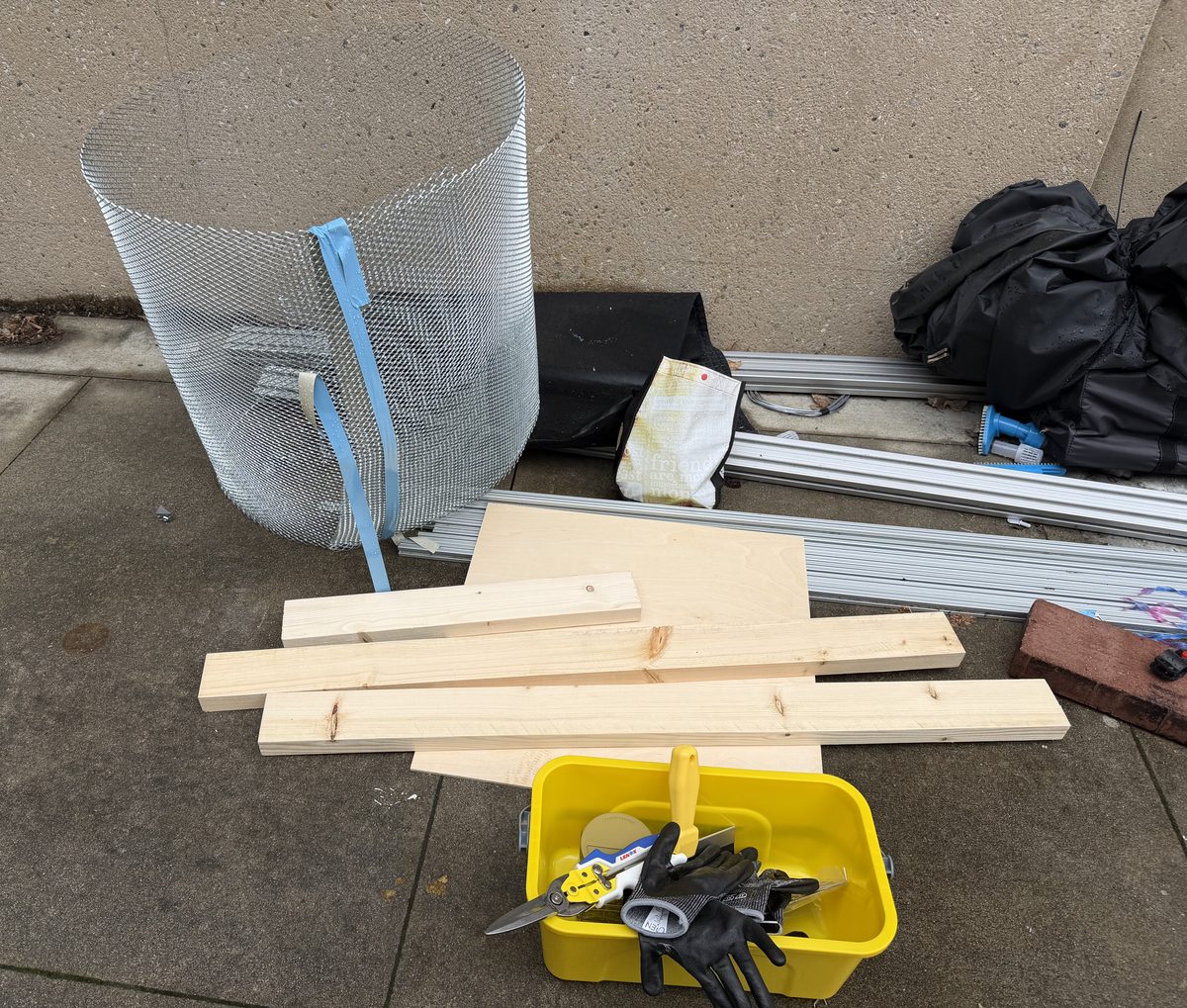
Two walls for the climbs on hardware. A rough stucco panel, close to a real outdoor wall, for the spines to grip, and a full-height wall on an aluminum-extrusion frame.
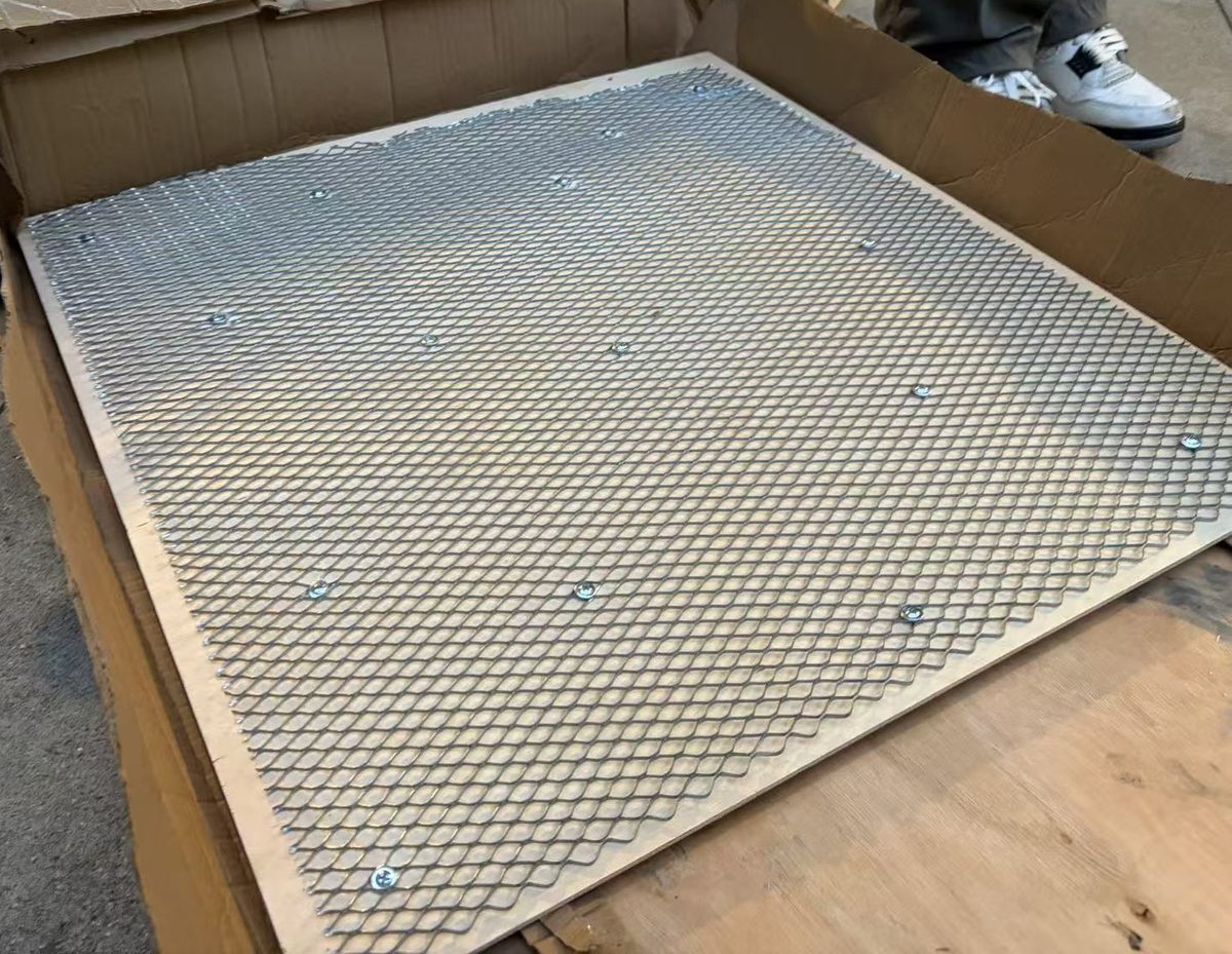
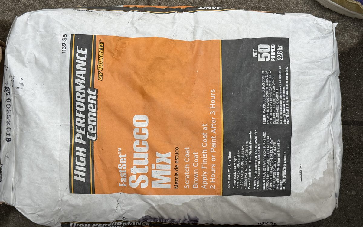
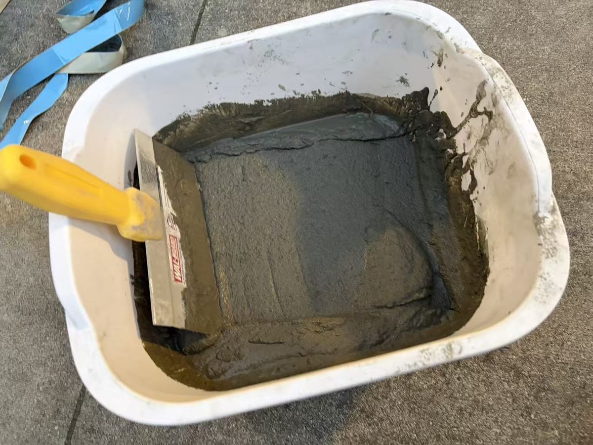
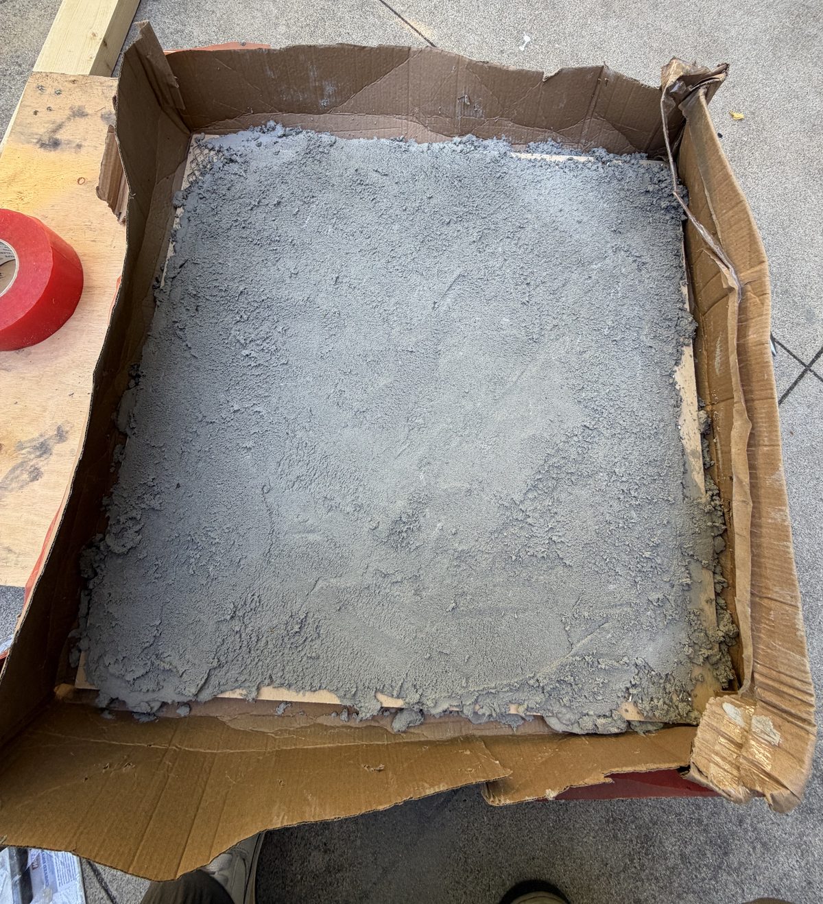
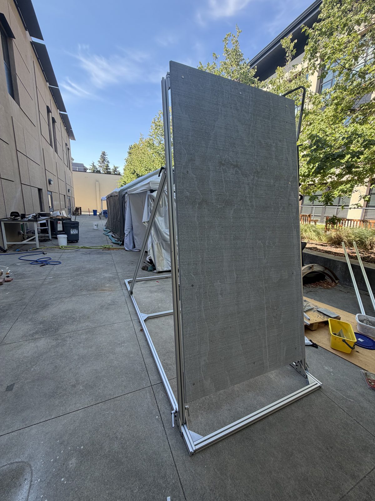
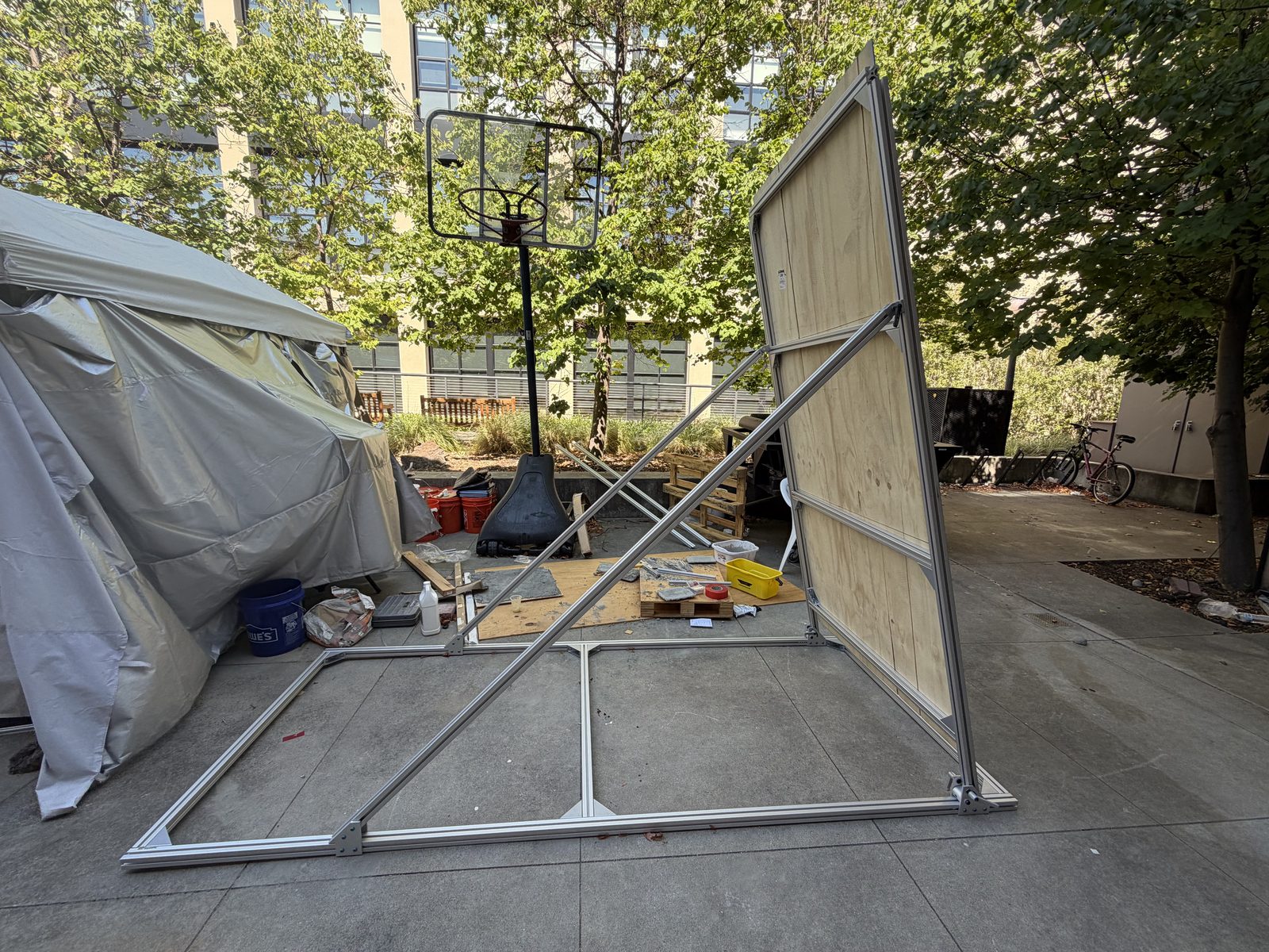
Supplementary
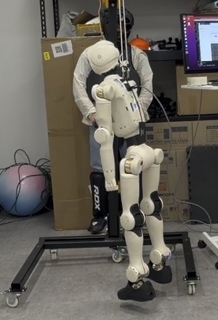
Suspended, feet unloaded.
Cubic trajectory from the power-on pose.
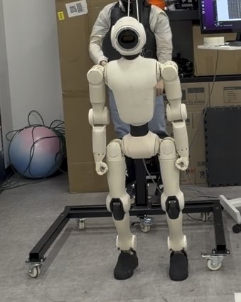
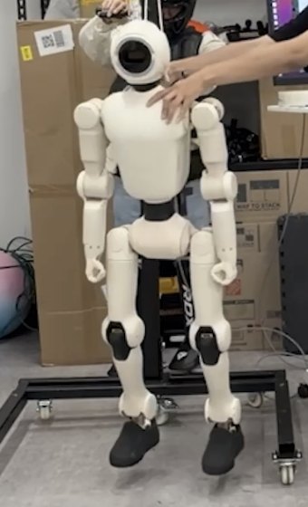
Feet loaded, gantry slack.
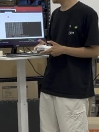
Gamepad, LT + RT.
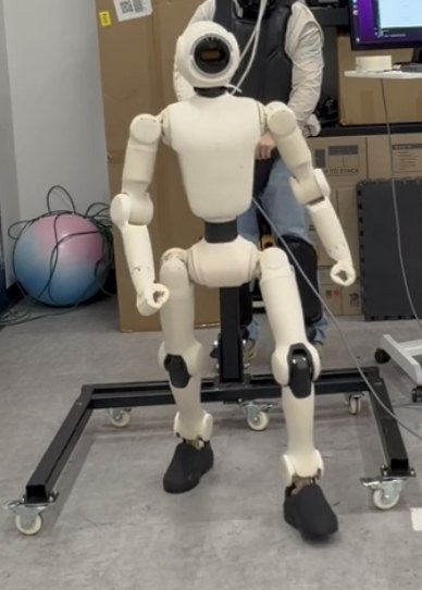
The control loop below.
Return to ZERO first, then hoist up.
Going to ZERO interpolates from the power-on pose with zero joint velocity at both ends: \(q(s)=q_{\mathrm{init}}+(q_{\mathrm{ZERO}}-q_{\mathrm{init}})(3s^2-2s^3)\), with \(s=t/T\).
One control loop, for robot and simulator
Status key
A mark on a clip says how far its task has come. Clips without a mark are complete as shown.
A generated or scripted reference motion. No policy has been trained on it yet.
Block flip · exterior corner
A trained policy that so far runs only in simulation. It has not been deployed on the robot.
Ground to wall · vertical wall
Paper in preparation
1Stanford University2Cornell University
†Co-corresponding authors